Float Switch Wiring Guide: NO vs NC Explained
Wiring a float switch correctly is essential for reliable automatic pump operation and water-level control. A float switch can use Normally Open (NO), Normally Closed (NC), and Common (COM) contacts depending on its design and the requirements of the control circuit.
In this guide, you’ll learn what NO, NC and COM mean, how float-switch contacts work, how to identify the correct terminals, how to test a float switch, common wiring mistakes and what to consider when wiring a float switch for a water or dewatering pump.
Safety note: Float-switch wiring can involve electrical circuits located around water. Always disconnect and isolate electrical power before working on wiring. For mains-voltage installations or unfamiliar control circuits, use a qualified electrician and follow the specific float-switch, pump and control-panel manufacturer’s wiring instructions.
Quick Answer: How Do You Wire a Float Switch?
A float switch is wired according to its contact configuration and the control logic required by the pump system. NO (Normally Open) contacts are open in the normal switch state and close when the switch operates, while NC (Normally Closed) contacts are closed in the normal state and open when the switch operates. A COM (Common) terminal is used with NO or NC contacts where the switch provides those terminals.
The correct connection depends on the specific float switch, pump, control circuit and required operating logic. Always identify the terminals from the product’s wiring diagram or datasheet before making a connection.
At a glance
| Term | Meaning | Basic contact state |
|---|---|---|
| NO | Normally Open | Open in normal state |
| NC | Normally Closed | Closed in normal state |
| COM | Common | Shared switching terminal |
Important: NO and NC are not universally “better” or “worse.” The correct choice depends on how the pump or control system is designed to operate.
What Is a Float Switch and How Does It Work?
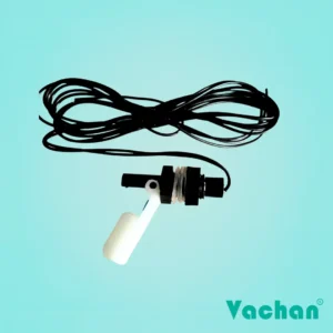
A float switch is a liquid-level sensing device that uses the movement of a float to operate an electrical switch.
As the water or liquid level changes, the float moves. When the float reaches its switching position, the internal switching mechanism changes the state of its electrical contacts. The resulting signal can then be used by a pump control circuit, controller, relay or other equipment.
Float switches are commonly used for:
- Water-level control
- Automatic pump operation
- Sump pumps
- Dewatering pumps
- Drainage systems
- Water tanks
- Sewage and wastewater applications
- Industrial liquid-level monitoring
The physical movement of the float and the electrical state of the contacts work together. Therefore, both the mechanical installation and electrical wiring need to be correct for reliable operation.
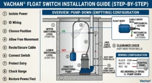
For installation and positioning guidance, see How to Install a Float Switch: Step-by-Step Installation Guide.
What Do NO, NC and COM Mean on a Float Switch?
Understanding the three terms is the foundation of float-switch wiring.
What Does NO Mean?
NO stands for Normally Open.
A normally open contact is open in the switch’s specified normal state. When the float operates the switch, the contact changes state and closes.
In simplified form:
Normal state → Open
Switch operates → Closed
The actual pump action depends on how the NO contact is connected within the control circuit.
What Does NC Mean?
NC stands for Normally Closed.
A normally closed contact is closed in the switch’s specified normal state. When the float operates the switch, the contact changes state and opens.
In simplified form:
Normal state → Closed
Switch operates → Open
Again, the resulting pump action depends on the control circuit.
What Does COM Mean?
COM stands for Common.
On a float switch that provides COM, NO and NC terminals, COM is the common connection shared by the switching contacts.
The circuit can typically be completed through either:
COM + NO
or
COM + NC
depending on the desired switching logic.
The exact terminal arrangement should always be confirmed from the specific product documentation.
NO vs NC Float Switch: What’s the Difference?
The difference between NO and NC is the electrical state of the contact before the switch operates.
| Feature | Normally Open (NO) | Normally Closed (NC) |
|---|---|---|
| Normal contact state | Open | Closed |
| Contact changes to | Closed | Open |
| Can be used for pump control? | Yes, depending on system | Yes, depending on system |
| Best choice | Depends on control logic | Depends on control logic |
| Main consideration | Required switching behavior | Required switching behavior |
The important point
There is no universal rule that says NO should always be used for pumps or NC should always be used for pumps.
The correct contact depends on:
- Pump control design
- Controller or control panel
- Relay/contactor arrangement
- Desired pump logic
- Required fail-safe behavior
- Float-switch specifications
- Electrical ratings
Always check the wiring diagram for the actual float switch and the pump/control system.
Float Switch Wiring Diagram
A float switch should generally be considered part of a control circuit, rather than automatically being treated as a direct motor connection.
A simplified control arrangement can be represented as:
Float Switch
↓
Control Circuit
↓
Relay / Contactor / Controller
↓
Pump
The actual arrangement varies between pump systems.
NO contact concept
In a simplified NO arrangement:
COM → NO → Control circuit
When the float reaches the operating position, the NO contact changes state and allows the control circuit to respond.
NC contact concept
In a simplified NC arrangement:
COM → NC → Control circuit
When the float reaches the operating position, the NC contact changes state and the control circuit responds accordingly.
Important wiring warning
These are conceptual diagrams, not universal wiring instructions.
The actual connection must be based on:
- Float-switch wiring diagram
- Pump wiring diagram
- Control-panel design
- Electrical ratings
- Required control logic
Never connect a float switch to a motor circuit simply by matching wire colors or copying a generic diagram.
How Does a Normally Open (NO) Float Switch Work?
A normally open float switch has its relevant contact open in the normal state.
When the float moves to its switching position, the internal mechanism changes the contact state.
The simplified sequence is:
Normal position
↓
NO contact open
↓
Float moves
↓
NO contact closes
↓
Control circuit responds
The control circuit may use this change to initiate a pump operation, stop a pump or trigger another action.
The specific result depends on how the switch has been integrated into the control system.
Example
If a controller is designed to start a pump when a particular contact closes, an NO float switch can provide that switching signal when the float reaches the required position.
However, the same physical float movement can produce a different result in another control system.
How Does a Normally Closed (NC) Float Switch Work?
A normally closed float switch has its relevant contact closed in the normal state.
When the float reaches its switching position, the contact changes state and opens.
The simplified sequence is:
Normal position
↓
NC contact closed
↓
Float moves
↓
NC contact opens
↓
Control circuit responds
NC arrangements can be useful where the control system is designed to react to an opening contact.
They can also be incorporated into control circuits where a particular contact state is required for normal operation.
The appropriate configuration depends on the complete electrical system rather than the float switch alone.
Should I Use NO or NC for My Pump?
The answer depends on the pump’s control system.
Before selecting NO or NC, check:
1. Pump control logic
Determine whether the system expects a contact to open or close when the float operates.
2. Control panel
Check whether the pump uses a dedicated float-switch input or an external relay/contactor arrangement.
3. Existing float switch
If replacing a float switch, check the configuration of the existing system before selecting the replacement.
4. Fail-safe requirements
Some systems may be designed around a particular contact state so that an open or closed circuit indicates a particular operating or fault condition.
5. Product documentation
Always check the manufacturer’s wiring instructions.
Simple rule
Don’t choose NO or NC based only on the pump brand or on a generic internet diagram. Choose the contact configuration required by the actual control circuit.
How to Wire a Float Switch to a Water Pump
A float switch can be used to provide a switching signal to a pump-control system, but the actual electrical arrangement varies significantly between pump installations.
A typical system may contain:
Float switch → Controller/relay → Contactor → Pump
In some applications, the float switch may connect to a dedicated controller input rather than directly switching the pump.
Why does this matter?
The electrical contact rating of the float switch must be suitable for the circuit it is switching.
A pump motor can draw significant electrical current, particularly during startup. A small float-switch contact should not automatically be assumed to be capable of switching a motor directly.
For this reason, some pump systems use a relay or contactor between the float switch and motor circuit.
Before wiring, check:
- Float-switch contact rating
- Pump voltage
- Pump current
- Control-panel design
- Relay/contactor requirements
- NO/NC configuration
- Manufacturer wiring instructions
For detailed physical installation and positioning information, see How to Install a Float Switch: Step-by-Step Installation Guide.
Float Switch Wiring for Dewatering Pumps
Dewatering pumps often operate in demanding environments such as:
- Construction pits
- Sumps
- Drainage areas
- Excavation sites
- Basements
- Wastewater areas
- Industrial drainage systems
Float-switch wiring in these applications requires attention to both the electrical system and the physical environment.
Protect the cable
Dewatering environments can expose cables to:
- Water
- Mud
- Debris
- Mechanical movement
- Sharp surfaces
- Repeated handling
Route the cable securely and prevent it from becoming tangled with the float or pump.
Protect cable-entry points
Moisture protection is particularly important around cable-entry and connection areas. Suitable grommets, sealing arrangements and strain relief should be used where required by the installation.
Consider pump movement
The float and cable should be positioned so that pump vibration or movement does not pull, crush or damage the cable.
Check float movement
The float should have enough room to move between its switching positions without contacting the pump, sump wall, pipework or debris.
A reliable dewatering installation therefore depends on more than simply selecting NO or NC. The float, cable, control circuit and pump must work together as one system.
How Many Wires Does a Float Switch Have?
The number of wires or terminals depends on the float-switch design.
Some switches may provide a simple switching arrangement, while others may provide access to different contact configurations such as:
- COM
- NO
- NC
A product may also have a cable configuration designed specifically for its intended application.
Therefore, wire count alone should not be used to determine how a float switch should be connected.
Before wiring:
- Check the product label.
- Check the wiring diagram.
- Check the datasheet.
- Identify the terminals or conductors.
- Confirm the required control configuration.
How to Identify NO, NC and COM Wires
If the float switch provides COM, NO and NC contacts, identify them from the manufacturer’s documentation before connecting the switch.
Step 1: Check the product markings
Look for markings such as:
COM / NO / NC
Step 2: Check the datasheet
The manufacturer’s documentation should take priority over generic wiring information.
Step 3: Check the wiring diagram
Confirm which conductor or terminal corresponds to each contact.
Step 4: Test the switch if appropriate
A suitable continuity test can help verify the switching behavior of an isolated switch.
Do not rely only on wire color
Wire colors are not a universal method for identifying NO, NC and COM across all float switches.
Always verify the specific product’s documentation.
How to Test a Float Switch With a Multimeter
A multimeter can be used to check the switching behavior of a suitable float switch when the switch has been safely isolated from the electrical circuit.
General testing procedure
1. Isolate the switch
Disconnect or isolate it according to the manufacturer’s testing instructions.
2. Set the meter
Use an appropriate continuity or resistance setting.
3. Check the normal position
Observe the contact state.
4. Move the float
Move the float through its operating range.
5. Check the contact state again
The relevant contact should change state when the float reaches its switching position.
6. Compare the result
Compare the observed behavior with the manufacturer’s specified NO/NC configuration.
What if the contact doesn’t change?
Possible causes include:
- Faulty switch
- Restricted float movement
- Internal switch damage
- Cable fault
- Incorrect test setup
- Incorrect identification of the contacts
Never use a multimeter as a substitute for following the manufacturer’s electrical safety instructions.
10 Common Float Switch Wiring Mistakes
1. Confusing NO and NC
Using the wrong contact can cause the pump to operate opposite to the intended control logic.
2. Ignoring COM
On switches with COM/NO/NC contacts, the common terminal must be correctly identified.
3. Assuming wire colors
Different products can use different conductor-color arrangements.
4. Copying a generic wiring diagram
A diagram found online may not match the pump or control panel being used.
5. Ignoring the contact rating
A float switch should not be assumed to be suitable for switching a particular electrical load without checking its rating.
6. Connecting directly to a pump motor without checking the circuit
Some systems require a relay, contactor or controller.
7. Failing to isolate power
Never work on live wiring around water.
8. Leaving connections exposed to moisture
Poorly protected connections can become unreliable in wet environments.
9. Not testing the float after wiring
A correct-looking connection can still have the wrong switching behavior.
10. Replacing a float with an incompatible configuration
A replacement switch must match the mechanical and electrical requirements of the existing system.
What Happens If a Float Switch Is Wired Incorrectly?
Incorrect wiring can cause several symptoms.
Pump does not start
The control circuit may not be receiving the expected switching signal.
Pump does not stop
The selected contact configuration may not match the required control logic.
Pump operates opposite to expectations
NO may have been used where NC was required, or vice versa.
Pump cycles unexpectedly
The issue may involve the float position, switching logic, water movement or control configuration.
Float appears to work but pump doesn’t respond
The fault may be downstream of the float, such as:
- Relay
- Contactor
- Controller
- Control-panel wiring
- Pump circuit
A float switch is only one part of the complete control system.
Why Does a Float Switch Keep Turning the Pump On and Off?
Repeated pump cycling does not necessarily mean the float switch itself is faulty.
Possible causes include:
- Float installed too close to a wall
- Insufficient switching differential
- Turbulent water
- Incorrect float positioning
- Cable interference
- Debris around the float
- Incorrect control configuration
- Water level fluctuating around the switching point
In dewatering applications, turbulence around the pump can sometimes cause the water level to change rapidly around the switching point.
Check the physical installation and control logic before replacing the switch.
For more information, see Why Your Dewatering Pump Keeps Running.
Is NO or NC Better for a Float Switch?
Neither configuration is universally better.
The appropriate choice depends on the application and control-system design.
NO may be appropriate when:
The control circuit is designed to respond when the relevant contact closes after the float operates.
NC may be appropriate when:
The control circuit is designed to respond when the relevant contact opens after the float operates.
The decision should consider:
- Required pump logic
- Control-panel design
- Relay/contactor arrangement
- Fail-safe requirements
- Existing wiring
- Float-switch specifications
The correct question is not “Is NO or NC better?” but “Which contact configuration does this control system require?”
Float Switch Wiring Troubleshooting
| Problem | Possible cause | What to check |
|---|---|---|
| Pump does not start | Incorrect contact configuration | NO/NC requirement |
| Pump does not stop | Wrong switching logic | Control circuit |
| Float does not switch | Mechanical obstruction | Float movement |
| Intermittent operation | Cable or connection issue | Cable and terminals |
| Pump operates unexpectedly | Incorrect wiring | Wiring diagram |
| Moisture near connection | Poor protection | Cable entry/sealing |
| Pump cycles rapidly | Float/control setup | Switching range |
| Replacement behaves differently | Incompatible switch | Product specifications |
Before troubleshooting electrical connections, safely isolate the power and follow the applicable manufacturer’s instructions.
Frequently Asked Questions About Float Switch Wiring
What is the difference between NO and NC on a float switch?
NO means Normally Open and NC means Normally Closed. NO contacts are open in the normal switch state and close when the switch operates, while NC contacts are closed in the normal state and open when the switch operates. The appropriate configuration depends on the pump or control circuit and the switching behavior required by the application.
How do you wire a float switch to a pump?
A float switch is wired according to the pump’s control circuit and the float’s contact configuration. The switch may connect to a controller, relay or contactor rather than directly switching the pump motor. Before making a connection, identify the required NO/NC configuration, check the electrical ratings and follow the wiring diagrams supplied with the float switch and pump system.
Which wire is common on a float switch?
On a float switch that provides COM, NO and NC contacts, COM is the common switching terminal. However, the physical conductor or terminal assigned to COM varies between products. Do not identify the common wire based solely on its color. Check the specific float switch’s label, wiring diagram or datasheet.
Can a float switch be wired directly to a pump?
Whether a float switch can directly control a pump depends on the electrical rating of the switch and the pump’s control arrangement. A small float-switch contact should not automatically be connected directly to a pump motor. Some systems use a relay, contactor or controller between the float switch and pump. Always check the manufacturer’s electrical specifications.
How do I know whether to use NO or NC?
Determine whether the pump control circuit expects the float operation to produce an open or closed contact. Check the pump/control-panel documentation and the float-switch wiring diagram. If replacing an existing switch, also verify the configuration of the existing system before selecting the replacement.
How do I test a float switch?
After safely isolating the switch, a suitable multimeter can be used to check whether its contact state changes as the float moves through its operating range. The result should be compared with the manufacturer’s specified NO/NC behavior. If the contact does not change state, inspect the float for mechanical obstruction and check the switch and cable for damage.
Why does my pump stay on when the float switch is connected?
A pump that stays on can be caused by incorrect NO/NC selection, incorrect wiring, restricted float movement, a control-circuit problem or a fault elsewhere in the pump system. Check the float’s physical movement and verify the wiring against the manufacturer’s diagram before assuming that the float switch itself is defective.
Why does my pump turn on at the wrong water level?
Incorrect switching levels can result from the float’s mounting position, insufficient float travel, cable arrangement, mechanical obstruction or the configuration of the control system. Check the installation position and switching range and compare them with the requirements of the pump system.
Can I replace an NO float switch with an NC float switch?
Not automatically. An NO and NC switch can produce opposite contact behavior, so replacing one with the other may change how the pump control system operates. Before making a replacement, confirm that the control circuit can accommodate the new configuration or that the switch is wired using the appropriate contact arrangement.
What happens if a float switch is wired incorrectly?
Incorrect wiring can cause the pump to remain on, remain off, operate at the wrong level or behave unpredictably. It can also create an electrical safety issue if the circuit is not connected according to the equipment specifications. Isolate the system and check the wiring against the manufacturer’s documentation.
Looking for a Float Switch for Your Pump?
The correct float switch depends on more than its physical size. The switching configuration, electrical requirements, cable arrangement, operating environment and pump compatibility should all be considered before selecting a product.
Vachan® manufactures float switches and water-level sensing solutions for applications including pump automation, water-level control and dewatering systems.
If you are replacing an existing float switch or selecting one for a new pump installation, share the pump brand/model, application, required quantity and existing float-switch details with Vachan.
Request a Quote
Related Float Switch & Pump Guides
Continue exploring Vachan technical resources:
- How to Install a Float Switch: Step-by-Step Installation Guide
- Float Switch Not Working: Common Fixes
- Why Your Dewatering Pump Keeps Running
- Signs Your Float Switch Needs Replacement
- Round vs Rectangle Float Switch: Which One Should You Choose?
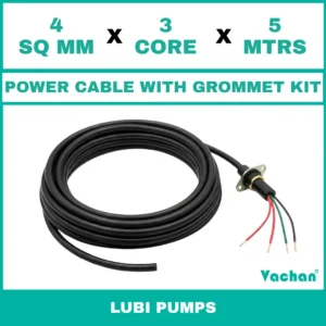
- How to Choose the Right Power Cable Kit
Conclusion
Correct float-switch wiring is essential for reliable automatic pump operation. Understanding the difference between NO, NC and COM helps installers identify the appropriate switching arrangement, but the correct connection ultimately depends on the specific pump control circuit and float-switch design.
Before wiring a float switch, identify the correct terminals, verify the required control logic, check the electrical ratings and follow the manufacturer’s documentation. After installation, test both the float’s mechanical movement and its electrical switching behavior.
For dewatering pumps and other wet-environment applications, also pay close attention to cable routing, moisture protection, float movement and mechanical interference.
If you need help selecting a float switch for a specific pump or application, contact Vachan® with your pump and application details for the appropriate solution.